Showing posts with label homemade. Show all posts

Friday, July 5, 2013

3D Clay Extruder

  My first 3D Printer 

a clay printer

I have been messing around for a while at the Brookside Cabinet Shop in Bethleham Connecticut and the Connecticut Hackerspace in Watertown Connecticut. It has been both educational and fun but I figure I had better start producing useful (or at least a little interesting) things before people start getting tired of hearing me talk. So, since the hackerspace has some machinery and the cabinet shop has machinery, well as materials, a giant CNC, and a new Pottery Shop (the 550 Gallery). I figured I should make a 3D printer, one that prints in clay.

First I looked around the web to see what others have done.

There is some pretty good information out there. Some of the links are to powder type printers. They look promising but I have decided to work on a printer with an extrusion type printer.

This is what I have come up with.


 It is just a piece of 3/4" PVC stuck to a board and a screw with a plunger turned by a stepper (and a planetary gearbox I pulled out of a broken cordless rotary saw) to push the clay out a nozzle at the bottom of the PCV. The little stepper at the top of the picture on the right was a little to small and I borrowed a NEMA 23 motor to really get things to work.

The plunger was not quite tight enough in the PVC. You can see 2 or 3 inches of clay that slipped around the plunger in the picture on the left. So, I have added a hot glue gasket that works well.

Here are a few things I have made. Most of my work has been to make the hardware and I still have work to do to get the software end of things working.


I have also posted a video on Youtube (My 3D Printer in action). I hope to make some more improvements and post some more information about it soon. Enjoy.
 

Tuesday, August 21, 2012

Gary's 2nd DIY CNC Touch Probe.

I made a little, fairly simple, touch probe for my little CNC a few months ago. I have been meaning to get back to it to make some improvements, maybe building a little better version, but one thing after another came up and I never got around to it. Finally, a couple days ago I started thinking about a new probe. What I came up with is different than the first but it works well. It still has some weaknesses but one of these days I will try again.

The earlier probe had some problems. For one, sometimes after making contact with the sample it would stick open. While stuck open it triggered EMC2 at the start of the next probe, and the next. This meant that it skipped over much of the area and left stripes in the data.

Also, the old probe took a fair bit of pressure to trigger. The sharp point on the end of the probe combined with the need for the probe to press a little hard on the surface to trigger meant it could mare softer surfaces. This was not really a problem for what I was using it for but it made scanning delicate things impossible.

Leaf Switch


With these two drawbacks of the old design and wanting to get something build quickly and inexpensively I started work. First, I looked in a bunch of old electronic junk I had laying around for some sort of switch. I found a small leaf switch that looked just about right. It is made up of a springy piece of metal with a contact over a ridged piece of metal with a contact. The two contacts are normally touching and very little pressure is needed to break contact.
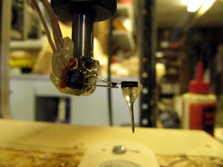


Leaf switch, little nail, broken bit and lots of hot glue.


To make the probe, I just used a little hot glue to glue a small nail to the springy piece part of the switch. Then I with some more hot glue I glued that all to a broken 1/4" router bit (I have a couple of those floating around unfortunately). I soldered a cable to the contacts on the switch (it takes two conductors, one ground and one for +5V). Then I hooked it up to the motor controller (see my old project on how to do this).


I made a change to the g code for EMC2 to use. It is all well and good that the old code scans a rectangle but I want to scan a dime. The dime is round and using a square pattern takes to much time. So, I broke out the trig I have learned over the years and got the CNC to scan in a circle. Again, it may not be the best example of gcode but it works for me.

<gcode>
G94 f15       ; feed inches/min

#1 = 0.00        ; X min
#2 = 0.00        ; Y min
#3 = 0.740        ; X max 0.99
#4 = 0.740       ; Y max 0.99
#5 = 0.04          ; Z max
#6 =-0.025         ; Z min
#7 = 0.002         ; X step
#8 = 0.002         ; Y step

#12 = #2           ; Y position
#13 = [#3 / 2]     ; hypotenuse

G0 Z #5
(PROBEOPEN probeResults.txt)
#12 = [-1 * #13]
O1 Do
  #14 = [#13 * cos[asin[ #12 / #13]]] ; end x
  #15 = [-1 * #14] ; start x
  O2 Do
    G0 X #15 Y #12
    G38.3 Z #6
    G0 Z #5
    #15 = [#15 + #7]
  O2 While [#15 le #14]
  #12 = [#12 + #8]
  O4 If [#12 / #13 le 1]
    #15 = [#13 * cos[asin[ #12 / #13]]] ; start x
    #14 = [-1 * #15] ; end x
    O3 Do
      G0 X #15 Y #12
      G38.3 Z #6
      G0 Z #5
      #15 = [#15 - #7]
    O3 While [#15 ge #14]
  O4 EndIf
  #12 = [#12 + #8]
O1 While [#12 le #13]
(PROBECLOSE)

G0 Z #5
G0 X #1 Y #2
M2
</gcode>


Results:
It works.
I scanned a dime and it took all night for the above code to get the job done. The blue in the image of the dime are places where the probe did not contact anything before the end of the probe run. The grey is, of course the dime. The red is where it was triggered at the start of the probe run. I think a bug got stuck under the probe (I was sleeping when it happened).

There are still issues to be dealt with. If you look close the edge of the coin came out pretty jagged. This seams to be because nail I was using as the probe stylus is to flexible. Well, it will give me something to work on.

Sunday, March 27, 2011

Making Homemade Foot Pegs for My KLR 650

Making Homemade Foot Pegs for My KLR 650

Not to long ago I fell while riding my motorcycle and while I was not terribly hurt (mostly my pride) the motorcycle did suffer some damage. One of the things that needed attention was one of the foot pegs. The rubber from the stock peg was ripped off. Not wanting to shell out the bucks for new pegs and wanting to start building things for myself I thought this would be a nice project.

So, I went out to take a look at what was on the bike (a KLR 650) and look to see what was available online as well as what other people have built.

The first link I saw was a post on KL650.net by a guy that milled some pegs out of aluminum. They look pretty sharp and he said something about making some more to sell if there was enough interest in them.
interest thread for klr650 foot pegs
That looked good and I recently got a little CNC machine but I did not have any aluminum around and the CNC I have is small. It uses a dremel tool for the spindle and it might take all year to cut that much aluminum. So, I looked some more.

Next I saw these.
Homemade Steel Foot pegs for the KLR
This is a little more along the lines of what I was thinking. So I went out and started looking for some steel. There is plenty of stuff laying around my parents place but I could not find anything square tubing that was the right size so decided to cut the ends off the stock pegs. I cut up the other bits of steel that I had collected together and got to welding.

Except for the square pieces I found all of it just laying around. I used flat bar for the outside body of the peg and a piece for a middle bar. There is a little piece of angle iron for a cross bar and to attach the square tubing to the rest of the peg. The square piece from the stock peg already had a hole in it and I figured that would make things easer as I would not have to drill holes in the correct spot to fix the bike.

The older gentleman in the picture is my father. There is an arc welder in the shop but the acetylene torch was pretty easy. He started welding a few years back in Flores ville High School at the ag shop building things for farmers down there. I got in on the welding also. It wasn't to hard, in fact it was sort of fun.

Some of my welds were not really pretty but I think they will hold. It might even give them a little character. Things need to be really hot to start emitting light.

Don't want to much character. I also wanted to cut notches on the top of the pegs to help my shoes stay on the pegs. So, I got out the grinder and got to grinding.


After the pieces were stuck together I cleaned them up some and sprayed some paint on them and put them on the bike. They fit, mostly. They don't fold back like they should so I will do a little more grinding (and a little more painting). They are a little rough but seem to work fine. So, now I have built something for the motorcycle and am looking forward to doing more. There is still a matter of a broken taillight and the fall also ripped some of the plastic off the bike and I suppose state safety inspection (Texas) needs to be done. It will be nice to get back on the road.