First 3D printer from the Connecticut Hackerspace.
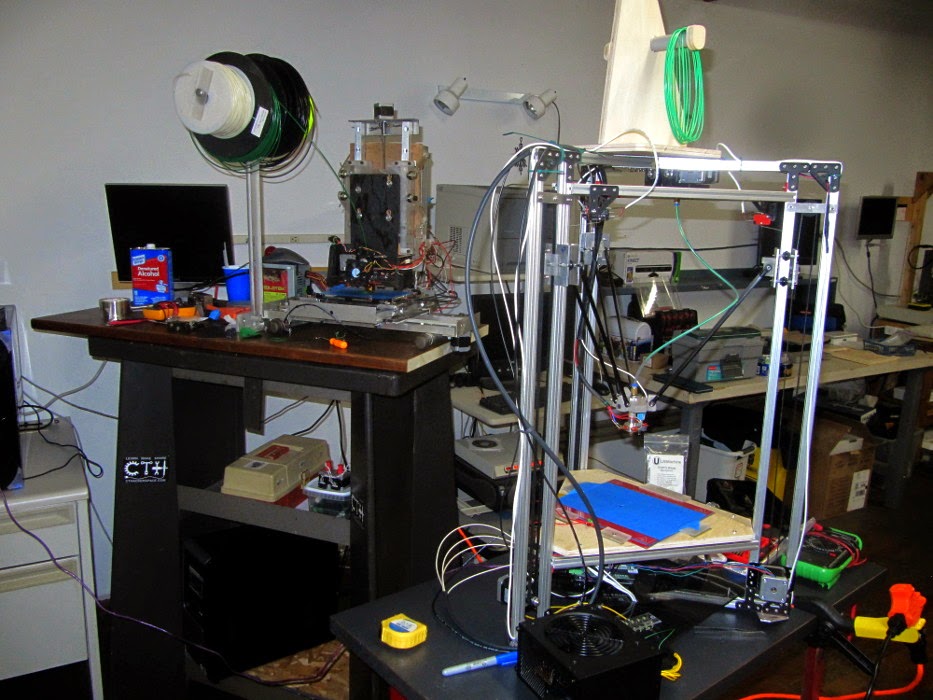
A few years ago I was a member of the Connecticut Hackerspace in Watertown Connecticut. It is a nice workshop pretty big with some pretty nice tools available. One of the tools that the space has is a little 3D printer that was built by members when CTH was first being formed. In some ways it does not look like much. It very much looks like it was made from odds and ends found in dark corners of a workshop. I never saw it print anything until
recently. It seems that as first built it was a little slow (it used
treaded rod to move the three axis). As it sat unused some parts were
scavenged for other projects and it fell into disrepair.
Recently the little printer has had some work done to it and it prints again. The threaded rod that controlled the movement was replaced with timing belts, parts were replaced, and other general upgrades and fixing up were done. Now it is working. It may not be the best printer in the world but it is certainly one of my favorites. It is the sort of thing that really demonstrates how little it takes to make a 3D FDM printer and how much fun the printers can be.
As neat as this little printer is there is a newer possibly more capable printer on the way. It is a delta style printer and still needs some work but it is not far from being finished. I am looking forward to seeing what it can do.
Saturday, July 5, 2014
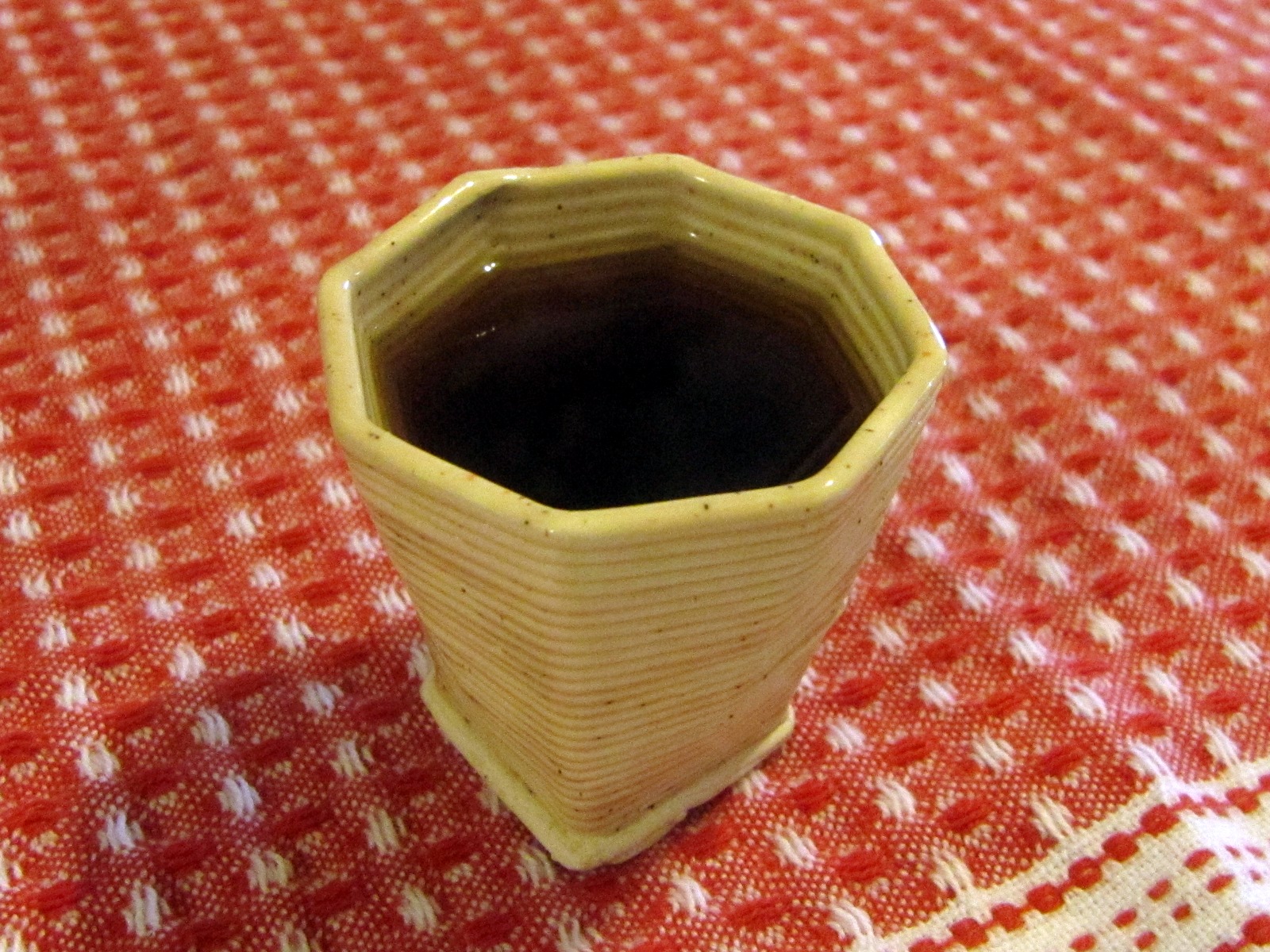
I have a 3D printer that prints clay and made this little vase. I want
to sell it on Etsy and thought it would be nice to make an animated GIF
to show it off on all sides. Etsy, though, does not allow animated Gifs
(maybe it is a good idea to limit there use). Facebook also seams to
limit the use of animated GIFs. So, I am putting it here to see if it
works.
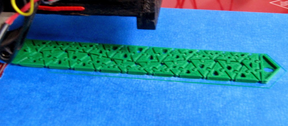
The pattern on the outside is based on a very simple diffusion limited
aggregation algorithm
(http://en.wikipedia.org/wiki/Diffusion-limited_aggregation) and created
with a program that I wrote. Diffusion-limited_aggregation can be found
in a variety of natural systems including mineral growth and electrical
discharge, as well as others. The organic forms created may look like
some types of seaweed or coral.
I was inspired by some other example of diffusion limited
aggregation.
Bit Player is a blog by Brian Hayes that I like to check now and again. He has a bunch of interesting articles on math and science and new ways of looking at things. The banner at the top of the page is based on the DLA pattern. Bit Player: An amateur’s outlook on computation and mathematics
Nervous Systems is a generative design studio creating, and selling some pretty amazing things based on algorithmically designed products and art. I think they are an example of the direction 3D printing can do a really good job. They have applications that allow customers to generate absolutely unique custom jewelry. Nervous Systems
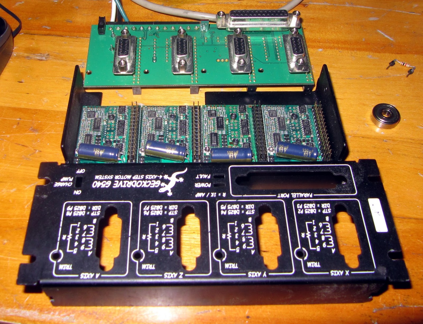
After about a month of dealing with a broken cnc and controller I have finally gotten my second clay extruder working. My Gecko G540 stepper controller blew a fuse. It uses a soldered in 7 amp fuse and is not the sort of thing I can get locally. So I ordered a few and when they came in I soldered one in and ... one channel of the controller was not working. So, I ordered another G250 from Geckodrive. I also sent an email to Gecko and they said send in the bad G250 and they will evaluate it, fix it (if possible), and send it back. I have not done so yet but I would like to offer a thank you to gecko for offering great customer service. In the picture of the drive you can see the bearing that started my month worth of trouble.
Second Clay Extruder
The new extruder looks nicer and works well but has some troubles. It will work until I get a third, hopefully better, built. The lower platform is too big and I can only print one thing at a time. If I try and printing a second something after printing a first more than 1 1/2" tall the lower platform bumps into the thing I first printed. This will be an easy fix. The other problem is that the clay leaked out the side of the PVC pipe when I start printing. I ended up hot gluing the pipe into the printer to stop this from happening. It works but it will be a little extra trouble when I have to put more clay into the tube. Still, the whole thing is about 10" shorter than the last one and holds about 4 times more clay.
Flower in unfired vase.
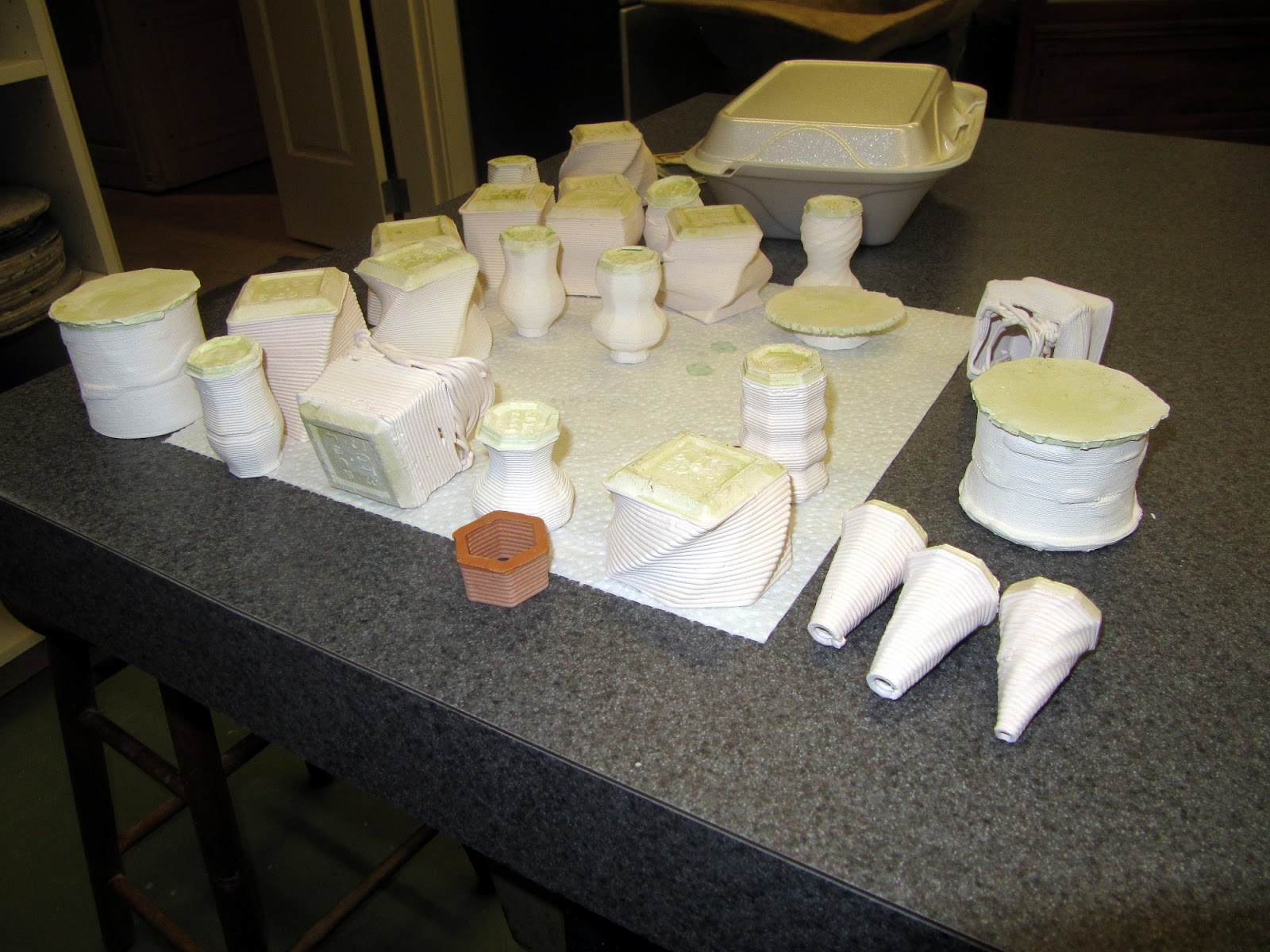
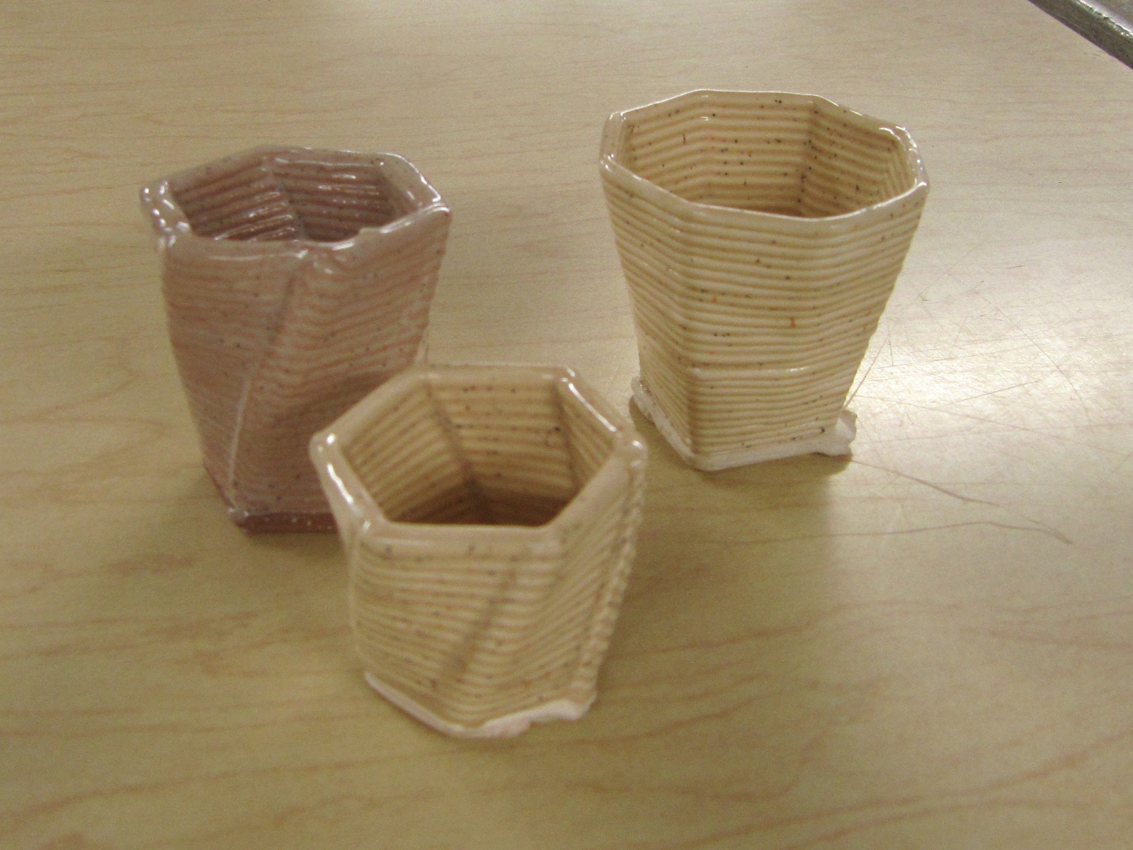
Here are a few pictures I took of things I have printed with my first extruder. They were mostly just experimental shapes but I did manage to sell three of them. The picture with just three things are the three I sold. Sorry some of the pictures are upside down. I was putting "resist" on the bottoms. Apparently, when I glaze them the glaze came flow down the side and then stick to the bottom of the kiln. I have painted the glaze on about half and I hope to get the rest done this week.
I have been messing around for a while at the Brookside Cabinet Shop in Bethleham Connecticut and the Connecticut Hackerspace in Watertown Connecticut. It has been both educational and fun but I figure I had better start producing useful (or at least a little interesting) things before people start getting tired of hearing me talk. So, since the hackerspace has some machinery and the cabinet shop has machinery, well as materials, a giant CNC, and a new Pottery Shop (the 550 Gallery). I figured I should make a 3D printer, one that prints in clay.
First I looked around the web to see what others have done.
There is some pretty good information out there. Some of the links are to powder type printers. They look promising but I have decided to work on a printer with an extrusion type printer.
This is what I have come up with.
It is just a piece of 3/4" PVC stuck to a board and a screw with a plunger turned by a stepper (and a planetary gearbox I pulled out of a broken cordless rotary saw) to push the clay out a nozzle at the bottom of the PCV. The little stepper at the top of the picture on the right was a little to small and I borrowed a NEMA 23 motor to really get things to work.
The plunger was not quite tight enough in the PVC. You can see 2 or 3 inches of clay that slipped around the plunger in the picture on the left. So, I have added a hot glue gasket that works well.
Here are a few things I have made. Most of my work has been to make the hardware and I still have work to do to get the software end of things working.
I have also posted a video on Youtube (My 3D Printer in action). I hope to make some more improvements and post some more information about it soon. Enjoy.
Saturday, October 27, 2012
Driving a Floppy Drive Brushless Motor
I took apart an old floppy drive a while back and in it I found a really nice looking motor. At first I though it just looked nice but I would never get it to run. I thought about throwing it away but then thought "It's cute maybe I will do something with it one day." and threw it in a box with a bunch of other junk that I might do something with one day.
Well, the day has come for the little brushless motor.
The first thing I did was look around and see what was on the Internet (I could become an instant expert). Google has lots of hits on "floppy drive motor" and "brushless motor" and they were not really what I was looking for. I had discarded the circuit board (probably in the box of junk some where) and would need to drive the motor directly with my own driver circuit. Finally, I ran across a link at eLABS called "Driving a three-phase brushless DC motor with Arduino - Part 1. Theory" witch led to "Brushless DC (BLDC) motor with Arduino – Part 2. Circuit and Software". They are wonderfully written and really got me and the motor on my way. Most of what I am writing is how I got the motor to turn a little bit. eLABZ's write-up is more complete and has a lot more on how and why the motors work.
This is just a little project to get the motor to turn. It is not going to power a quadrocopter or a motorcycle but it should get the motor turning without much effort. It might even be a learning experience, it certainly was for me.
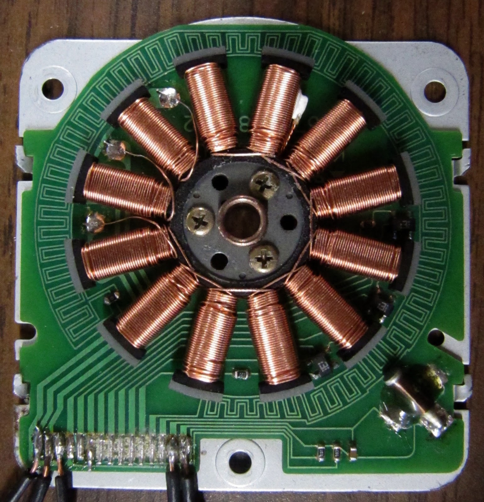
The motor
First thing I did was try to find out what each pin on the motor was for. There are 15 pins and to date I have only identified three of them. The first three (see figure #) are to the coils. The last two pins (14 and 15) got to the big sensor that I think is a hall effect sensor (I have not hooked this up yet). That leaves 10 pins unaccounted for but I think they are to more sensors to get position and/or speed information.
Pins
Function
Nice picture
1
to coil set #1
2
to coil set #2
3
to coil set #3
4 - 13
???
14
Vin for big hall effect sensor ?
15
output for big hall effect sensor ?
When I started, I expected to see two pins for each set of coils. Instead I found only one pin to each set of coils (there are 12 coils, three sets of four). One end of each set of coils goes to it's pin. The other end is tied to the other two sets of coils. Reading a little about brushless motors I found out why.
So, there are 6 or 7 ohms of resistance between any two pins because the path between the pins goes through two sets of coils. This is sort of nice because I will only need 1/2 h-bridge to drive each set of coils. Each pin will be set either positive (+5V) or negative (to ground). You can see where the coils are tied together two pins to the right of the glob of solder that goes to pin #1.
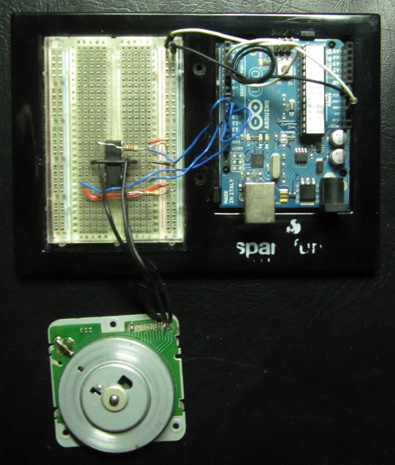
I got out my Ardiuno and set up a little circuit wrote a little program and watch what happened.
The circuit
First I hooked everything together. I had some L293D quadruple high-current half H-bridge drivers. I could have used discrete transistors but these were sitting there and are all ready to go. I only needed three of the four half h-bridges. The only other components I used were two 1kOhm resistors. I put it all together on a breadboard and wired it to the Arduino.
Hook up three Arduino pins (9,10,11) to three of the "In" pins on the L293D (2, 9, 12).
Put 1000k resistors (Brown, Black, Red) between the two "Enable"
pins on the L293D (1, 11) and the 5V supply on the Arduino. .
The L293D pins 4, 5,
12 and 13 get grounded.
I also hooked the Arduino 5V supply to the Vs
and Vss pins on the L293D
The L293D pins 3, 6, and 14 got to the motor pins 1, 2, and 3.
Pins 10 and 11 on the L293D are not used (it is the half H-bridge that it not used).
The breadboard and schematic were both made using software from Fritzing. It is really easy to use and I think the results are nice (despite my lack of skills in this area).
The three coils can be hooked up how ever you like. If you get it wrong it might turn backwards. This is because there are only six ways to hook them up. Three of the ways are ABC, BCA, and CAB. The other three ways are just a mirror of the first three, CBA, ACB, and BAC. So, if you get the motor turning and you would like for it to turn the other was you could just switch any two of the three wires.
The Program
I wrote a really simple program to drive the motor. It is not meant to be used in any sort of application. It was written to make the motor turn and it works...sort of. Below is a listing for the program. you should be able to copy it directly and nake it work. There are comments in the program (parts with "//" in front of it) that might make reading it easer.
// These are the pins used to drive the motor.
int pinA = 9;
int pinB = 10;
int pinC = 11;
int step = 0; // Keeps track of what pulse width to use
unsigned long lastTime = 0; // the time in micros since last step
int period = 5000; // set motor speed by defining time between steps
void setup()
{
// Set pins as digital outputs
pinMode(pinA, OUTPUT);
pinMode(pinB, OUTPUT);
pinMode(pinC, OUTPUT);
// Set all the pins LOW
digitalWrite(pinA, LOW);
digitalWrite(pinB, LOW);
digitalWrite(pinC, LOW);
}
void loop()
{
// Check if it is time for the next step
if ((micros() - lastTime) >= period)
{
// Next three lines send pulse width value for this step.
analogWrite(pinA, levels[step]);
analogWrite(pinB, levels[(step + 16) % 48]);
analogWrite(pinC, levels[(step + 32) % 48]);
// Add one to set (% 48 rolls step back to 0 after it fits 47)
step = (step + 1) % 48;
// make note of current time
lastTime = micros();
// ramps up the speed
if (period > 500)
{
period -= 1; // make speed faster (the period between steps smalled)
}
}
}
It is a very simple program meant to get the motor to turn. It starts out slow (and not very smooth) and get faster (ans finally runs smoothly).
The top part of the program defines
variables These variables are:
levels:
This is the pulse width values (arduino PWM). It is a look-up table and it means the Arduino can just look the value up in this table instead of calculating it each time (these calculations take time, I just did it in another program so the Arduino would not have to.
pinX:
These three define the pin numbers for the Arduino's output.
step:
This keeps track of where to look in the look-up table.
lastTime:
The last time the step was changed.
period:
How long to wait after the lastTime to step again.
Then comes the setup function for the Arduino. It gets everything ready for the main loop. The first there lines set the pinX pins as outputs and then there are thee lines that sets them "LOW" or makes them 0 voltage.
Then then comes the main loop function. This should not be confused with "a" loop (such as a "for" loop or a "while" loop). It is "the" loop and everything that happens in this loop keeps happening until you unplug the Arduino.
The first line of the main loop checks if enough time has lapsed to move to the next step. It checks with an "if" statement. It uses micros(), a clock that keeps track of how long the Arduino has been on in microseconds. Subtracting lastTime from the time returned with micros() gives the time since the last step. If it is longer than the period then it takes the next step.
The next step (the next three non commented lines) is to write the PWM from the lookup table to the output pins with analogWrite. The first argument (in parentheses) is the pin to write to. The second argument is the value found in the look up table. pinA gets the value of the variable step (the arduino starts counting at 0). When step = 0 the value is 127. pinB gets the value at step + 16. The "% 48" uses the Arduino's modulo operator. It makes sure that the value of step + 16 is not bigger than 47 because there are only 48 values in the look up table(remember the Arduino starts counting at 0. 0 to 47 is 48 values). pinC gets the value at step + 32.
The modulo operator might seem a little confusing but it really makes things easer. Imagine having to write into the program something to deal with step + 16 being bigger that 47. The fact that the Arduino starts counting at 0 might be a little confusing but ... that is the way it is. Computers are like that.
Then the program increments the step by on.
Then it makes note of the current time using micros().
Then there is another if statement that checks if the motor is
spinning at the maximum speed yet (the shortest period). If not it
subtracts one from period until the period is 500 (that is 500
microseconds between steps).
And that is it. Upload the program to the arduino and watch it run. There is still work to be done to make it run smoother and faster but it turns.
I tried the same technique on a little hard drive motor and it ran really well (sorry no video yet).
There are a few things I would like to change. I think it is under powered and would run better (especially at lower speeds) if I used a power source other than the 5V from the Arduino. I would like to add some speed control to it, maybe a potentiometer, to make it a little more fun. Of course it would be nice to run in both directions with the same program (I just need to have it step backwards through the PWM levels). The coils on the motor look nice and I think I will cut windows in the spindle so they can be seen at the motor turns.
I made a little, fairly simple, touch probe for my little CNC a few months ago. I have been meaning to get back to it to make some improvements, maybe building a little better version, but one thing after another came up and I never got around to it. Finally, a couple days ago I started thinking about a new probe. What I came up with is different than the first but it works well. It still has some weaknesses but one of these days I will try again.
The earlier probe had some problems. For one, sometimes after making contact with the sample it would stick open. While stuck open it triggered EMC2 at the start of the next probe, and the next. This meant that it skipped over much of the area and left stripes in the data.
Also, the old probe took a fair bit of pressure to trigger. The sharp point on the end of the probe combined with the need for the probe to press a little hard on the surface to trigger meant it could mare softer surfaces. This was not really a problem for what I was using it for but it made scanning delicate things impossible.
Leaf Switch
With these two drawbacks of the old design and wanting to get something build quickly and inexpensively I started work. First, I looked in a bunch of old electronic junk I had laying around for some sort of switch. I found a small leaf switch that looked just about right. It is made up of a springy piece of metal with a contact over a ridged piece of metal with a contact. The two contacts are normally touching and very little pressure is needed to break contact.
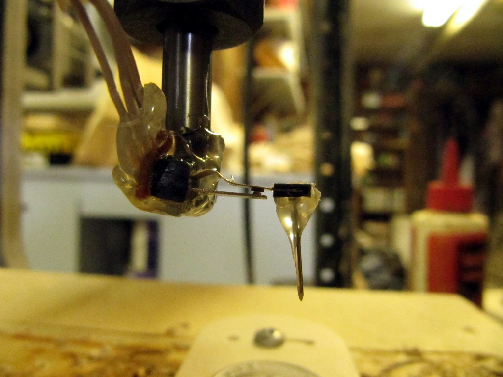
Leaf switch, little nail, broken bit and lots of hot glue.
To make the probe, I just used a little hot glue to glue a small nail to the springy piece part of the switch. Then I with some more hot glue I glued that all to a broken 1/4" router bit (I have a couple of those floating around unfortunately). I soldered a cable to the contacts on the switch (it takes two conductors, one ground and one for +5V). Then I hooked it up to the motor controller (see my old project on how to do this).
I made a change to the g code for EMC2 to use. It is all well and good that the old code scans a rectangle but I want to scan a dime. The dime is round and using a square pattern takes to much time. So, I broke out the trig I have learned over the years and got the CNC to scan in a circle. Again, it may not be the best example of gcode but it works for me.
<gcode>
G94 f15 ; feed inches/min
#1 = 0.00 ; X min
#2 = 0.00 ; Y min
#3 = 0.740 ; X max 0.99
#4 = 0.740 ; Y max 0.99
#5 = 0.04 ; Z max
#6 =-0.025 ; Z min
#7 = 0.002 ; X step
#8 = 0.002 ; Y step
#12 = #2 ; Y position
#13 = [#3 / 2] ; hypotenuse
G0 Z #5
(PROBEOPEN probeResults.txt)
#12 = [-1 * #13]
O1 Do
#14 = [#13 * cos[asin[ #12 / #13]]] ; end x
#15 = [-1 * #14] ; start x
O2 Do
G0 X #15 Y #12
G38.3 Z #6
G0 Z #5
#15 = [#15 + #7]
O2 While [#15 le #14]
#12 = [#12 + #8]
O4 If [#12 / #13 le 1]
#15 = [#13 * cos[asin[ #12 / #13]]] ; start x
#14 = [-1 * #15] ; end x
O3 Do
G0 X #15 Y #12
G38.3 Z #6
G0 Z #5
#15 = [#15 - #7]
O3 While [#15 ge #14]
O4 EndIf
#12 = [#12 + #8]
O1 While [#12 le #13]
(PROBECLOSE)
G0 Z #5
G0 X #1 Y #2
M2
</gcode>
Results:
It works.
I scanned a dime and it took all night for the above code to get the job done. The blue in the image of the dime are places where the probe did not contact anything before the end of the probe run. The grey is, of course the dime. The red is where it was triggered at the start of the probe run. I think a bug got stuck under the probe (I was sleeping when it happened).
There are still issues to be dealt with. If you look close the edge of the coin came out pretty jagged. This seams to be because nail I was using as the probe stylus is to flexible. Well, it will give me something to work on.
This post has been updated. To see the updates look for the items in red labeled "Update".
I have been playing with a little CNC machine for about 2 years now and it has been fun. Still, as much fun as it has been, I think it would be nice if it started to pay for itself. So, I started to think about all the things I might make with a small (about 6.5"x6.5" cutting area) that I could sell. There are lots of ideas but after some considerations I have started making some light switch covers. After a little searching and a bunch of measuring I have a sort of basic template that I can start making covers with.
Before I settled on light switch covers I ran through many ideas. There are a few things I needed to keep in mind. I have a Zen Toolworks 7x7 inch CNC. (http://www.zentoolworks.com). So, what ever I make needs to have parts that will fit on the table. Also, I would like to start selling some things on Etsy pretty soon so nothing too complicated. A clock kit with lots of gears was one early idea. I have been working on this for a while and it will have to be a future story. I am really fascinated by the notion of a mechanical computer, something like a mechanical Arduino. This is also for the future. These things might be a little involved to be my first jump into making a little money with a CNC.
After some more thought I hit on switchplate covers. They should be pretty straight forward and I think there is a lot of room for customization. The plates in the hardware stores are pretty plain (even the fancy ones). After making a few plain plates there aught to be able to move into more involved designed. So, I got out a couple covers and started measuring.
(Update (Sept 26, 2012): The distance between the screw holes should read "2.375"))
The outside of the plates that I measured were 2 3/4"x4 1/5". The standard screws are #6x32 ovel head screws and would normally use a hole about 0.1440" but I just drilled 1/8" holes. They are a little tight but it is wood and does not present a problem and it holes the screw in place. The holes are 2 13/32" apart (that is center to center). I counter sunk the holes making the to diameter 1/4" and 3/32" deep. The hole for the toggle switch is 7/16" x 15/16". I am making the plates from 1/4 plywood and it might be a tiny bit thick but it works fine. I route out the back of the plate 1/8" deep and leave about 1/4" around the edge.
DXF file:
coming soon (I need to find a place to host the file) (Update (Sept 26, 2012): basicSwitchPlate.dxf.
This is a file in my github repository. To download the file look down the page and find the file called "basicSwitchPlate.dxf". Right click on the file and choose "Save link as ...". If you left click on the file the dxf will open in your browser and you will see the text file that makes up a dxf file. The distance in the dxf file between the screw holes has changed in the dxf file. It should be 2.375" .)
Gcode file:
Before you use the gcode take a look at it. It is what I am using but your setup is likely different. I used a 1/8" bit for the front of the plate. The bit I used for the back is a little less than 1/2". I think it is undersized to cut groves for 1/2" plywood to fit into.
I added little tabs so the plate does not break out of the plywood panel while it is cutting. There are four around the outside and two in the little piece that gets cut out for the toggle switch. Also, I call the subroutine to cut the screw holes twice. I find this helps make the holes smoother.
BasicFront.ngc
#1 = 0
; Set project vars and material vars #1 = 15.0; feed-rate #2 = 0.25; up #3 = 0.0; down #4 = 1; tool number for using the cutter diameter compensation #5 = 0.12500; cutter diameter for initial move #6 = #3; to keep track of current cutter depth #7 = -0.25000; material thickness #8 = 0.04100; cutter step - depth
; second hole ; counter sink hole #9 = 1.37500 ; center X #10 = 1.04687 ; center y #11 = 0.25000 ; max diameter #12 = 0.13000 ; min diameter #13 = -0.09000; depth O500 Call [#1] [#2] [#3] [#4] [#5] [#6] [#7] [#8] [#9] [#10] [#11] [#12] [#13] O500 Call [#1] [#2] [#3] [#4] [#5] [#6] [#7] [#8] [#9] [#10] [#11] [#12] [#13]
; Switch hole G0 X [1.15625 + #5] Y [2.25000 + #5] G41 D#4 G1 X 1.15625 Y 2.25000
O200 Do G1 Z #6 G1 X 1.15625 Y 1.78125 O201 If [#6 ge #7 + 0.0625] ; tab G1 X 1.59375 Y 1.78125 O201 Else G1 Z [#7 + 0.06250] G1 X 1.59375 Y 1.78125 G1 Z #6 O201 EndIf G1 X 1.59375 Y 2.71875 O202 If [#6 ge #7 + 0.0625] ; tab G1 X 1.15625 Y 2.71875 O202 Else G1 Z [#7 + 0.06250] G1 X 1.15625 Y 2.71875 G1 Z #6 O202 EndIf G1 X 1.15625 Y 2.25000 #6 = [#6 - #8] O200 While [#6 ge #7] G0 Z #2 G40 #6 = #3; reset working depth
; Outside G0 X [1.37500 - #5] Y [0.00000 - #5] G42 D#4 G1 X 1.37500 Y 0.00000
O201 Do G1 Z #6 G1 X 2.68749 Y 0.00000 G3 X 2.75000 Y 0.06250 I 0.00000 J 0.06250 O202 If [#6 ge #7 + 0.0625] G1 X 2.74500 Y 3.76284 ; tab O202 Else G1 Z [#7 + 0.06250] G1 X 2.74500 Y 0.37500 G1 Z #6 G1 X 2.74500 Y 3.38784 G1 Z [#7 + 0.06250] G1 X 2.74500 Y 3.76284 G1 Z #6 O202 EndIf
G1 X 3.28364 Y 3.76284 G3 X 3.32971 Y 3.86757 I 0.00000 J 0.06250 G1 X 1.41739 Y 5.95374 G3 X 1.33261 Y 5.95374 I -0.04239 J -0.04620 G1 X -0.57972 Y 3.86757 G3 X -0.53365 Y 3.76284 I 0.04607 J -0.04223 G1 X 0.00000 Y 3.76284
O203 If [#6 ge #7 + 0.0625] ; tab G1 X 0.00000 Y 0.06250 O203 Else G1 Z [#7 + 0.06250] G1 X 0.00000 Y 3.38784 G1 Z #6 G1 X 0.00000 Y 0.37500 G1 Z [#7 + 0.06250] G1 X 0.00000 Y 0.06250 G1 Z #6 O203 EndIf G3 X 0.06250 Y 0.00000 I 0.06250 J 0.00000 G1 X 1.37500 Y 0.00000 #6 = [#6 - #8] O201 While [#6 ge #7] G0 Z #2 G40 #6 = #3; reset working depth
; Go back to Initial position G0 Z #2 ; move cutter up G0 X 0.00000 Y 0.00000 ; move cutter up ; End File M2
BasicBack.ngc
#1 = 0
; Set project vars and material vars #1 = 17; feed-rate #2 = 0.5; up #3 = 0.0; down #4 = 4; tool number for using the cutter diameter compensation #5 = 0.46875; cutter diameter for initial move #6 = #3; to keep track of current cutter depth #7 = -0.12500; material thickness #8 = 0.0625; cutter step - depth
; Initial position G0 Z #2 ; G0 X 0.00000 Y 0.00000 G0 X 1.00000 Y 1.00000
; Inside Faceing G0 X 0.56260 Y 0.56260 #9 = 0.56260
O200 Do G1 Z #6 F#1 O201 Do G1 X #9 Y 0.56260 G1 X #9 Y 3.93739 #9 = [#9 + 0.23625] G1 X #9 Y 3.93739 G1 X #9 Y 0.56260 #9 = [#9 + 0.23625] O201 While [#9 le 2.43740] G1 Z #2 G0 X 0.56260 Y 0.56260 #9 = 0.56260 #6 = [#6 - #8] O200 While [#6 ge #7]
G0 Z #2 #6 = #3; reset working depth
; Inside Edge G0 X [0.18750 + #5] Y [0.18750 + #5] G42 D#4 G0 X 0.18750 Y 0.18750 G1 Z #7 G1 X 0.18750 Y 4.31249 G1 X 2.56249 Y 4.31249 G1 X 2.56249 Y 0.18750 G1 X 0.18750 Y 0.18750 G1 X 0.18750 Y 1.00000 G0 Z #2 G40
; Go back to Initial position G0 Z #2 ; move cutter up G0 X 0.00000 Y 0.00000 ; move cutter up ; End File M2
This seams to work ok for me. I have put a few up for sale on Etsy. Hopefully I will soon be making some more and slightly more elaborate plates.


