DIY CNC Touch probe
I got a little CNC machine a couple years ago and it has been fun to have around. I have cut out all sorts of little things. There is a mount for a Dremmel, a Kite Areal Photography (KAP images) rig, a bunch of wooden gears, some clocks, and other little stuff. Most recently, I have been working on a CNC touch probe. Originally the probe was to help me level the CNC table. It took a little effort and learning but now it is up and running (sort of) and I had to try it out. It is not perfect and there are things I am planning to do to it but I think I have an OK start.A touch probe for a CNC is a pretty simple device. Basically the touch probe is used with the CNC to measure distances of things mounted on the work platform. It mounts on the CNC where the cutter usually is and is moved in one direction, in the Z axis (up and down) for instance, until it touches something and it stops. After it stops it can record the position of the end of the probe to a file. If this procedure is repeated many time you end up with a "point cloud", a map of the hight of the object being measured. The point cloud can be used for many different things. It could be used to create a G-code program to copy the thing that has been measured. It could be used to make a picture or map and I am hoping it can be used to help level my CNC table.
I started out looking at some examples of homemade touch probes. There are a few pretty good ones on the Internet.
http://www.indoor.flyer.co.uk/probe.htm
http://www.brusselsprout.org/CNC/1P-Probe/
http://fadedbits.com/2011/02/touchprobe/
http://www.vinland.com/touch-probe.html
http://www.cnczone.com/forums/digitizing_laser_digitizing/22837-cheap_home_made_touch_probe.html
Expired patent for the Renishaw touch probe.
Google Patents
Some of the sites made things look a little intimidating but I was not looking for super accuracy. This is more of a proof of concept than anything else. So, I got started.
The design
Disclaimer:I am not a super a super engineer or anything. I just threw together the design below to see if I could get anything to work. So, if you try any of this be careful, don't poke out an eye or break anything.
Warning:
The drawings you are about to see are not the prettiest you have ever seen.
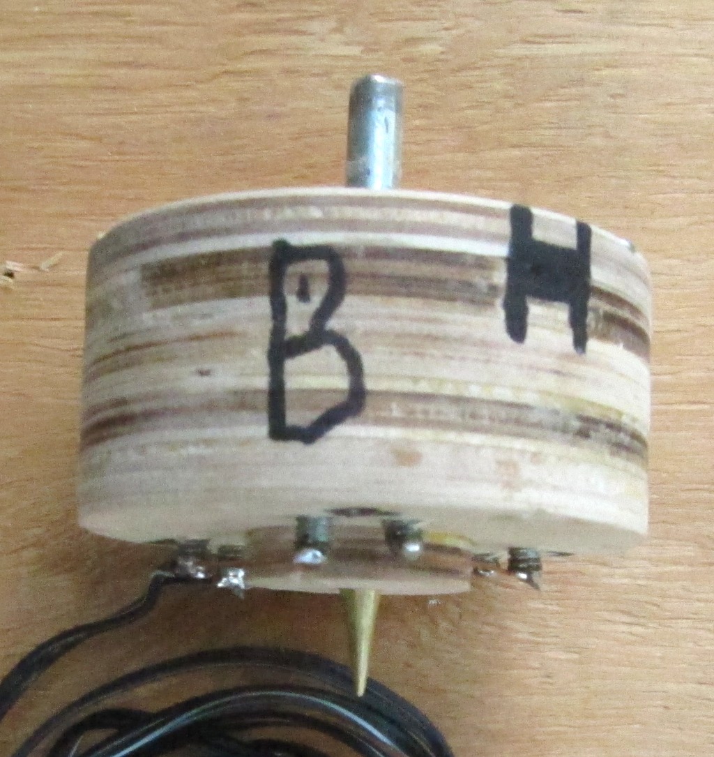
 The probe is very simple. It is just a switch that is normally closed and when the tip of the probe touches something it opens the circuit (breaking the connection) and sends a signal to the controlling software to stop probing. The probe tip is a little piece of brass rod sticking out the bottom of the body of the probe. The switch is three pieces of brass rod attached to the top of the probe (held together with non-conduction material, this case it is wood) resting on six screws. The screws are wired together and positioned so that the "switch" is closed normally and lifts up off the screws when it hits something.
 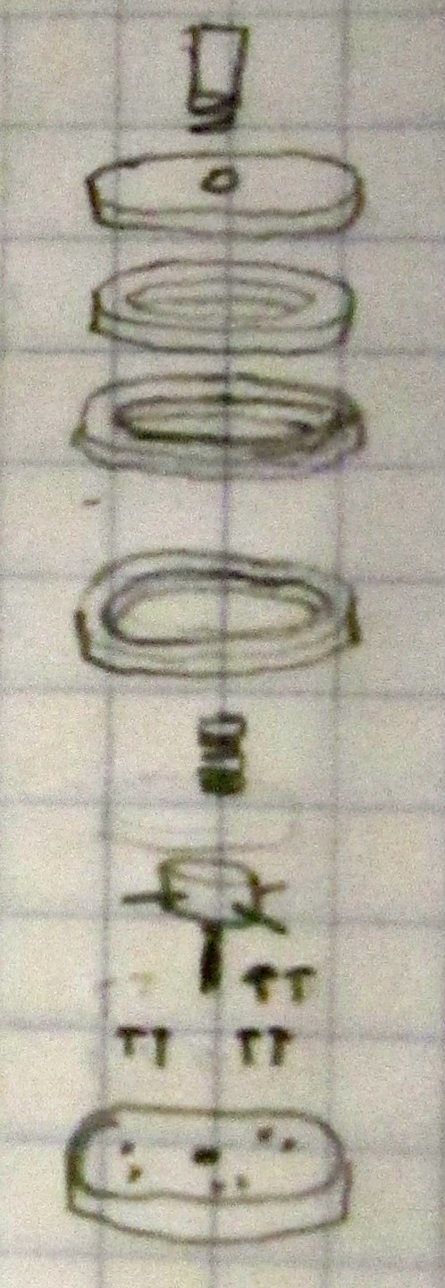 I cut the body out of 1/4" plywood. The body design is simple. The top and bottom are just round discs with some holes, the side is made out of rings, and the top of the probe are made from discs with groves for the brass switch rods and a hole in the center for the probe. I used a few 1/8" dowel pins to keep everything straight and a cut off 1/4" bolt as a shank to attach the probe to the CNC spindle. I wrote a few g-code files to cut everything out and got started.
  While the wood parts were being cut out I cut four pieces of 3/16" brass rod. One for the probe and three for the switches. I also looked around and found six screws with round heads for the rod to rest on. The heads are round so when the switch is closed the rod can make contact with the screws and when the probe lifts up just a little bit it breaks contact.
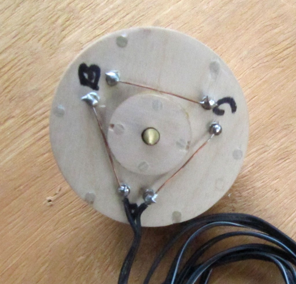 Then I soldered some wire to the bottom of the switch screws. One piece of wire between each set of screws and a couple pieces from a couple screws to the controller. The wire I used to hook up to the controller is long enough to reach from the CNC to the controller. I checked with an ohm meter that all the switches were closed (and adjusted the screws up and down to make them close).
Set Up
I am have a Zen Toolworks 7"x7" CNC put together from a kit. It is a little small but has worked out well and been fun.http://www.zentoolworks.com/product_info.php?products_id=74
The stepper motor controller is a Geckodrive G540 4 axis controller. I only have 3 axis but can dream of a forth.
http://www.geckodrive.com/g540-digital-axis-motor-control-p-39.html
As for software to run the CNC I am using EMC2 Ver. 2.4.3. It is free, works well, and runs on Linux. The last item is important as I do not have any computers that run on windows.
http://www.linuxcnc.org/
For a spindle I am using a Bosch Colt router with a 1/4" collet.
To set up the probe I first put put the probe in the router. The shank of the 1/4" bolt is a little small for the collet. Next time I will find something that fits better (I also want a better mount for the router, but that is another story). Please note that with the probe installed in the router it would be a mistake to turn the router on. Spinning at 16,000 RPM, the probe with a 2 foot piece of wire hanging off would, at the very least, make a mess of the project.
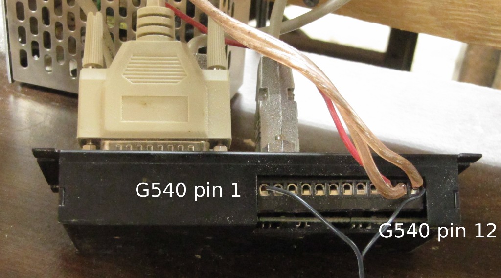
Next I hooked up the wires out of the probe to the G540 controller. One goes to pin 1 (corresponds to pin 10 on the parallel port) and the other to ground (pin 12 on the G540)
 To set up EMC2 I just used the stepper configuration program and chose to modify the set up I already had to run the machine without the probe. On the second screen of the set up wizard, "Parallel Port Set Up" I set pin 10 to be "Probe In". (At first I had pin 10 set to "Digital In", this is a mistake.) That was all the set up there was.
G Code
The sample program that came with EMC2 did not work for me. I don't know why. I did not try to figure it out. I just wrote another little gcode program that probed every position on a grid. It is not fancy but it worked for me.
I set the minimum Z (the deepest I wanted the probe to go) to a little above the table. I did not want the probe to miss something and keep going down.
G38.3 is the code to I used to probe (see the EMC2 users manual). You could also use G38.2. The difference is that G38.3 does not stop for probing errors like reaching the final probe depth and not hitting anything. G38.2 stops the program and reports an error and I did not want this to happen.
I used "G38.3 Z #6" to set the probe to probing. The "G38.3" tells the machine to use the probe. The "Z" tells the machine to probe in the Z direction (you can also probe sideways and other directions, to find the edge of a work piece). The "#6" (where #6 is set at the top of the program to equal 0.05") is as far down as I want the probe to go before stopping.
I added comments in the code, they should help understand the code. I tried to make everything readable but, well, it is not english.
I see not that I forgot to add a line to the top of the g code to tell it to run in inches. I forgot a few things but everything worked ok for me.
; probe.ngc
G94 f2 ; feed inchs/min
; Set up the grid that I want to scan.
; The XY min and max values set up the XY size of the grid
; Set up the grid that I want to scan.
; The XY min and max values set up the XY size of the grid
: The Z min max values define the start of the probing run
; and the end of the run if the probe touches nothing
#1 = 0 ; X min
#2 = 0 ; Y min
#3 = 0.7 ; X max
#4 = 0.6 ; Y max
#5 = 0.12 ; Z max
#6 = 0.05 ; Z min
#7 = 0.01 ; X step
#8 = 0.01 ; Y step
#11 = #1 ; X position
#12 = #2 ; Y position
; move the probe tip up so it does not run into anything
G0 Z #5
; open a file to record the probed results in
(PROBEOPEN probeResults.txt)
O1 Do ; O1 is a loop for X grid values (rows)
#11 = 0 ; set X to 0 at the start of each Y column
O2 Do ; O2 is a loop for the Y grid values (columns)
G0 X #11 Y #12 ; move to new grid position
G38.3 Z #6 ; probe down to the minimum Z value
G0 Z #5 ; raise the probe tip so it does not run into anything
#11 = [#11 + #7] ; add the X step to X, the next grid point.
O2 While [#11 le #3] ; keep this up until reaching the maximum X value
#12 = [#12 + #8] ; done with this row (Xs) move to next column (Ys)
O1 While [#12 le #4] ; keep this up intil reaching the last column (max Y)
(PROBECLOSE) ; close the probe file full of points
G0 Z #5 ; raise the probe tip so it does not run into anything
G0 X #1 Y #2 ; move to the start point
M2 ; end the g code
It turned out a better than I had feared it might and worse than I had hoped. I was not super careful in cutting parts out and putting them together. In fact I was rather cavalier about the whole thing. So, I was happy with what I got and confident I can do better next time.
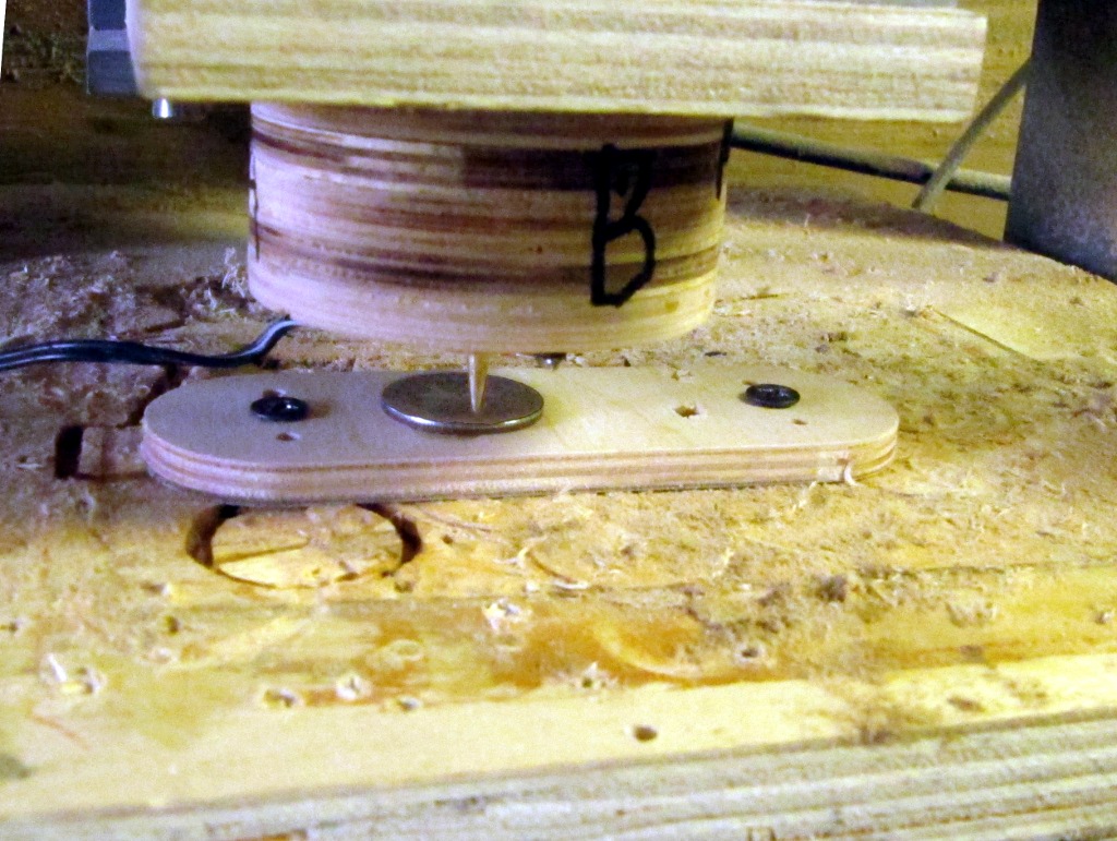 I built this thing to check that the CNC work surface is parallel to the X and Y axis of motion. If these axis are not parallel then the machine will cut deeper on one side of the work piece than the other and spoil what might otherwise be a nice piece of work. First though, I decided to test it by scanning a US Quarter. I glued a quarter to a piece of plywood, stuck it on the CNC table and got to scanning.
  For my very first attempt I set the scanning are to 1"x1" and the XY step between grid points to 0.005". This was way to slow for my tastes. So, I changed the scanning area to 0.7"x0.6" and scanned the center section of the quarter. One problem that I had was the probe would touch the quarter, open the switch, and then not close. This meant the switch was open at the start of the next grid point and would be triggered at the highest point. At times like this I reached in tap the probe and the switch would close. When this happened the machine recorded the top of the probe run (0.12", Z max in the gcode). That is what all the white stripes were are in the image.
 Epilogue
Like I said above, I am happy with the way things turned out. The next one will turn out better. I will be more careful with the construction and I believe that will help with the precision of the device. I also have an idea about how to make sure the switch closes after it is triggered. I think I will use three springs, one above each switch, to push the rod back down instead of the one spring in the center.
I hope this write up is helpful to some one. Let me know what you think. Take care and have a good time.
Gary
Update :(Oct 16, 2012: A while back I made another touch probe. It is much simpler and a description can be found on the blog (here).